


Heatsink
-
Posts
2303 -
Joined
-
Last visited
-
Days Won
23
Content Type
Profiles
Forums
Gallery
Everything posted by Heatsink
-
From the album: Heatsink's Photos
-
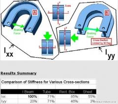
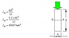
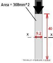
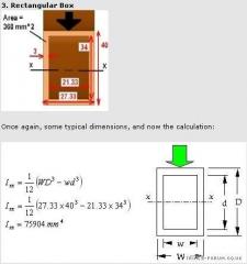
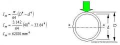
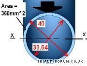
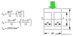
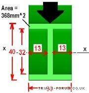
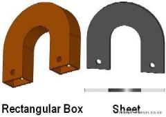
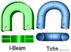
NOTE: Following requests, this is the same post with the pictures reloaded:) Sorry about the difference in picture size, this is due to the images being shrunk during abit of TF admin. Hopefully everything can be read ok! I've split this post into 2 parts aswell, because I reached the limit on the number of images you can put in 1 post! Brake Booster Theory Part1 of 2 Q: If I have a set weight of booster material, What cross section shape would be stiffest? Waffly bit You want to make a brake booster, partly because you don’t want to spend any more money on your bike (it’s already cost you an arm and a leg!) and also because it could be fun to do and cool to say that you’ve got a custom booster. You’ve noticed that these are commonly made out of Aluminium or steel, and you’ve managed to get hold of a big enough off cut for one of one of these metals. Your thinking is “Well if this material is stiff enough for those boosters out in the shops it should do the trick for me.” You may have a few tools in the shed, and we’re talking basic here like a hack saw and vice, probably not a CNCing station. All that remains is to design the blighter, with the requirements that it be sufficiently stiff to counter the flex in the bike frame, and be light weight. (What's "Light weight"? 100g? Up to you to decide. Have a look at existing boosters for an idea, but to get a feel for weight remember this useful rule of thumb - 100g is roughly the weight of 1 apple ) You’ve been searching for posts about home made boosters on TF and there’s a lot of conflicting advice about what shapes are stiffest. You realise that to transform your lump of metal into many of the shapes isn’t going to be possible to achieve without some sort of fancy equipment that you’d find in an Engineering company. With your simple tools, you know that your booster will probably end up being a simple horse shoe shape hack sawed out of sheet metal. Nevertheless, you’re interested in knowing which of the fancy cross-section shapes (I-beam, tube, rectangular box etc) is the stiffest and how they compare to the simple rectangle sheet that yours is probably going to be. The good news is you don’t need any fancy computer software (e.g. Finite Element Analysis, “FEA”) to tell you which shapes are stiffest. All you need is a calculator! The thing that you need to compare for the various shapes is a property called the Second Moment of Area measured in mm^4 (mm to the power of 4). Another name used for the same thing is the Moment of Inertia (In case you wanted to do some looking on the internet for yourself). Clever people (Mathematicians & Engineers etc) have a habit of giving things fancy sounding names to hide the fact that what they’ve discovered is actually rather simple. In short the Moment of Inertia, or I as we’ll call it since it saves my fingers from getting worn out, is a measure of a shape’s resistance to bending. The higher it is, the better as far as we’re concerned! If you want a closer look at the ideas behind the calculations coming up, check out This site, and do a search of your own for: "Second Moment of Area" "Moment of Inertia + Simple Cross Sections" You get the idea! If you do an internet search you’ll be able to find equations for all manner of shapes. For the shapes we’re looking at, I've pulled out the equations we need. Brake booster cross sections to compare The idea of arranging a set weight into a variety of shapes basically means that the cross-sectional area must be the same for all our boosters we're going to compare (Remember that Mass = Vol x Density, and Vol = c/s Area x Length. So for a constant density and length, Mass is proportional to c/s Area) I've calculated the dimensions of these shapes so that the height of the booster is always 40mm - Which is assuming that if the booster gets bigger than this it'll get in the way of your mini-seat/arse. To make things simple I've made the assumption that all our boosters have a constant shape along their whole length. This of course will mean that the arms of the booster will stick out too much and catch on your leg, but we're only interested in doing a stiffness comparison here, and not calculating deflections and forces. You'll notice that I've written "Ixx" instead of I in the calculations that follow. This simply describes the direction that the braking force is acting in, which is perpendicular to the line, the axis, that I've drawn on the pics ( X at both ends). If I could do subscript then the "xx" would be below the line. You could leave this XX out if you fancied, but once I'd done the comparison calcs I thought I'd compare the stiffness if the shapes were rotated around 90 degrees, about an YY axis. The XX and YY are therefore needed to make it clear which way round the calcs are for. Moment of Inertia Calculations 1. I-Beam Above are some typical dimensions. The line, x ---- x is the "Neutral Axis" around which bending is happening, and the big black arrow is the force from the brakes, trying to bend the booster. Using the equation for this shape, to find the Moment of Inertia: 2. Tube Above are some typical dimensions which keep the surface area the same as the I-beam. Here's the equation for a tube with the dimensions dropped in: >>> Part 2 in next post
-
From the album: Heatsink's Photos
-
From the album: Heatsink's Photos
-
From the album: Heatsink's Photos
-
From the album: Heatsink's Photos
-
From the album: Heatsink's Photos
-
From the album: Heatsink's Photos
-
From the album: Heatsink's Photos
-
From the album: Heatsink's Photos
-
From the album: Heatsink's Photos
1 -
From the album: Heatsink's Photos
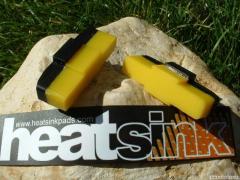
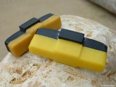
Looking good www.heatsinkpads.com -
From the album: Heatsink's Photos
These are sitting on a coffee table in Canada Quality photo by Roman, (Bruiser1) www.heatsinkpads.com -
From the album: Heatsink's Photos
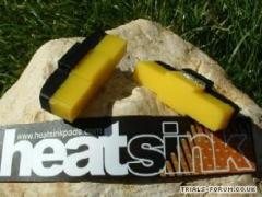
Pads on sale, info on www.heatsinkpads.com Each pad traded in takes £1 of the price of £12 - chance for free pads! 10mm of pad, hardness equal to Bloxx, many satisfied owners with ground, CD and normal rims. N.B. Not intended for Koxx Rims with their softer Alu -
From the album: Heatsink's Photos
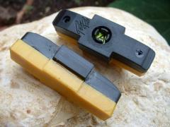
Small piccy -
From the album: Heatsink's Photos
1st ones -
From the album: Heatsink's Photos
First pics -
From the album: Heatsink's Photos
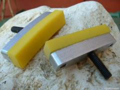
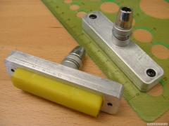
1. Retains pads securely during braking 2. Pads easily removed when worn out 3. Replacement pads nice and cheap 4. Machined Alu body with steel bosses for attaching to brake assembly Designed by me, made by Todge (Fresh Products - coming soon!) -
From the album: Heatsink's Photos
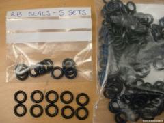
5 sets (10 o-rings) for £2 & you supply a Self Addressed Enveloped Send to: Stephen Spurgeon The Technology Partnership Melbourn Herts SG8 6EE -
From the album: Heatsink's Photos
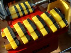
Pads on the production line -
From the album: Heatsink's Photos
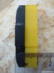
Hmmm 10mm -
From the album: Heatsink's Photos
Compared to Batch "A" with 6mm -
From the album: Heatsink's Photos
Batch "A" About to be sent -
From the album: Heatsink's Photos
Pocket money! -
From the album: Heatsink's Photos
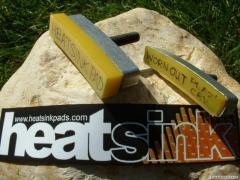
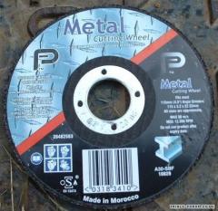
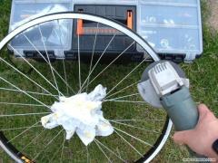
Grind.....