


Heatsink
-
Posts
2303 -
Joined
-
Last visited
-
Days Won
23
Content Type
Profiles
Forums
Gallery
Everything posted by Heatsink
-
Cracking Vid there Lee! I'm loving those Hook ups too ;) Good variety of moves and the vid's just the right length avoiding repetition. The only downside is you've set quite a standard to beat in your next one! Steve
-
Looking forward to seeing the EBTC fixtures calendar. I'm fancying having a go in my first Comp series!
-
From the album: Heatsink's Photos
-

From the album: Heatsink's Photos
-

From the album: Heatsink's Photos
-

From the album: Heatsink's Photos
-

From the album: Heatsink's Photos
Very first example - Actual items may have smaller front logo on the left breast with Team rider name underneath -

From the album: Heatsink's Photos
-

From the album: Heatsink's Photos
The little cutie! -
From the album: Heatsink's Photos
-
From the album: Heatsink's Photos
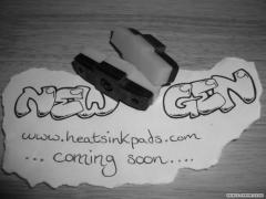
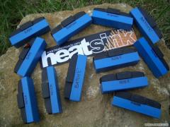
Details soon - www.heatsinkpads.com -

From the album: Heatsink's Photos
Mr & Mrs Spurgeon + Baby Callum Rhys born 5am 7th of Nov 2004 -
From the album: Heatsink's Photos
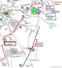
N.B. The route marked leads from Junction 11 of the M11 to a place where you can find plenty of free parking any time of the week Note the position of the Train station, which is the usual meeting point. See you in Cambridge soon -
From the album: Heatsink's Photos
-

From the album: Heatsink's Photos
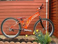
£35 posted including 2 Tioga tyres & pair of Heatsink brake pads & Heatsink stickers! Some scratches -
This was my form of resistance training :ermm: Kept me fit between 2000 and 2004!
-
From the album: Heatsink's Photos
Blimey this kept me fit! -
From the album: Heatsink's Photos
-

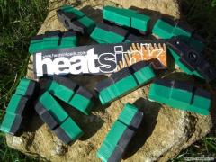
Batch "B" limited edition - 6 pairs up for grabs i
Heatsink posted a gallery image in Member Galleries
From the album: Heatsink's Photos
Comp ends Wed 13th of Oct Good luck! -
From the album: Heatsink's Photos
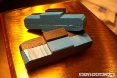
First pairs 6th Sept '04 - About to be glued Softer material than yellow pads! Out for testing in next couple of days -
From the album: Heatsink's Photos
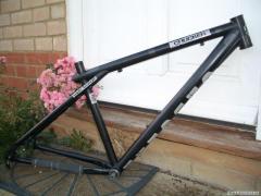
In pristine condition. Only some minor scratches underneath down tube. -

From the album: Heatsink's Photos
I couldn't resist -
From the album: Heatsink's Photos
-
From the album: Heatsink's Photos
-
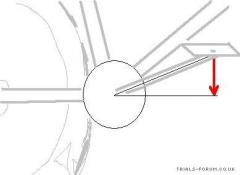
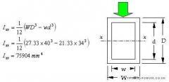
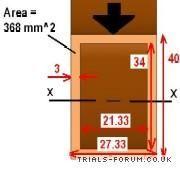
Brake Booster Theory Part 2 of 2 4. Sheet <img src='http://www.trials-forum.co.uk/gallery/1096150804/gallery_201_104_1096365568.jpg' border='0' alt='user posted image' /> This is the last one <img src='http://www.trials-forum.co.uk/gallery/1096150804/gallery_201_104_1096365593.jpg' border='0' alt='user posted image' /> We can take these results and see what they can tell us about actual boosters. For example: Any sheet type booster could be stiffer if the same weight of material can been arranged in an I-beam shape. Compare the shape of the Carbon Fibre boosters by Whitehurst or the Carbonique with the Shimano one! The stiffness depends on two things remember, the shape (as we've examined) and the material. It should be pointed out that the CF across these boosters doen't have the same stiffness behaviour. The thing about Carbon Fibre is that the material stiffness can be fantastic in one direction, and next to nothing in another. This depends on the way the fibres were laid out before being glued together to form the composite. Basically the fibres resist being stretched but coil up like spaghetti if compressed. There a great article which gives more details about Carbon Fibre here. Stiffness in other direction? Just out of interest, imagine we rotate the cross-sections around 90 degrees. How will their stiffness compare? In the calculations so far we have found Ixx, which means I (Moment of Inertia) about the XX axis. To find the stiffness when rotated around, we need to find I about the YY axis as shown on the pic below. I don't think it's worth putting the calculations up, since you've already got a flavour of how these are done in the text above. If you want to try these for yourself, you'll need to understand the "Principle of Parallel Axis" - Another posh name for something rather simple. Have a look at This site for an explanation. (The same one as listed earlier in the post) <img src='http://www.trials-forum.co.uk/gallery/1096150804/gallery_201_104_1096366605.jpg' border='0' alt='user posted image' /> Can I apply this "Moment of Inertia" stuff to bike frame tubes? Yep. Have a look at this webpage which uses the same method to look at frame tubing shapes. "Beam bending theory" This stuff really isn't that difficult to understand. Try doing some calculations for yourself and you'll get your head around it. The trick is I've found that nothing's that complicated when you're interested in it! ------------------------------------------------------------------------------------------- More useful info on the stiffness of boosters Well I spent a few days getting my head around shapes for stiffness by looking through old Uni notes and doing some calculations. Then I posted my results above... Now I want to simplify things into a couple of bite-sized, easy to remember morsels :D BITE SIZE #1 Imagine the beam shown below as part of the booster (a close up of the 12 o'clock position. So close that it would appear straight), with the bend from the braking forces exaggerated so you can actually see it! 1. The Neutral Surface - this middle surface sees no stress! <img src='http://trials-forum.farseer.net/newimages/neutralsurf1.jpg' border='0' alt='user posted image' /> 2. The Stress graph - Which shows that under braking forces the inner of the horse shoe is in tension, the top compression and the very middle (The Neutral Surface) stays the same! The stress rises the further out from the Neutral surface you move. Max compressive stress at outer surface A, Max Tensile stress at inner surface B <img src='http://trials-forum.farseer.net/newimages/neutralsurf2.jpg' border='0' alt='user posted image' /> Here's a sentence, lifted straight from my Uni notes, which summarises the whole thing in a nutshell: "Optimise the design by reducing the volume of material near the N.A." You want the material to be slapped at the furthest out points so that it is used to resist the biggest stresses which are to be found at the extremities. "I" has it, "l" doesn't!! Simple as....:) BITE SIZE #2 What effects stiffness? There are 2 things that decide it: The material's stiffness & the shape it's arranged into. You're pretty much stuck with the Young's modulus of Alu and Steel (A fancy grade of steel has the same stiffness as an indentically sized mild steel equivalent - little known fact!) For a chosen material then, the only way you can actually influence the stiffness is by working out the best shape to form your booster. Of course those best shapes are often in reality too expensive or even impossible to produce. A compromise needs to be found! This is a useful formula I found the other day in my Uni notes (A last useful after over 5 years since I graduated!) It shows clearly the effect of the two variables I've just mentioned on how bent a straight beam will become when a bending moment acts on it: M = EI/R Where M is the bending moment E, youngs modulus I is our new friend R is the bend radius of a once straight beam If M is set, (from braking force) E is set then we want as big a bend radius (Infinity = straight) as poss I.e. biggest I possible! - The wonders of old Uni notes which are suddenly interesting again. Q: What's a moment? A moment is Force x distance from the fixed point, I.e. if we stuck a ruler protruding off a desk with a few books on the last inch, then stuck an apple at some distance along the free end. The moment would be: Apple Weight (Newtons) x dist (m) In words, the force doing the bending, (the weight of the apple) multiplied by the distance from where the ruler is fixed by the books Just thought I'd try and simplify things because I do get a bit keyboard happy :"> Steve